I needed a script to send multiple values from Max/MSP to an Arduino to control a few components. After researching for a viable solution for my application, I had discovered that it is really easy to interface Max/MSP with an Arduino microcontroller by simply using the ‘serial‘ object built-in into Max/MSP’s objects library.
arduino-to-max.maxpat (Save Link As…)
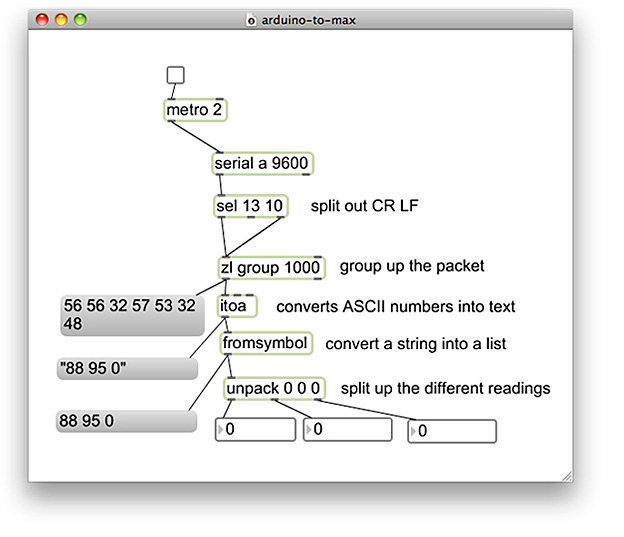
I put together a clean serial Max patch which simply uses the ‘serial‘ and ‘unpack‘ objects to get analog and/or digital values coming from Arduino into Max/MSP. This solutions makes it really easy to get serial values from your Arduino into Max/MSP by splitting up the different readings and outputting them into number-boxes.
To make the Max/MSP and Arduino serial patch work, you will also need to copy and paste a really simple Arduino syntax into a new Arduino sketch I put together below. You may alternatively download the Max/MSP and Arduino sketch.
int val1 = 0;
int val2 = 0;
int val3 = 0;

void setup()
{
  // start serial port at 9600 bps:
  Serial.begin(9600);
}

void loop()
{
  // read analog input, divide by 4 to make the range 0-255:
  val1 = analogRead(0);
  val2 = analogRead(1);
  val3 = digitalRead(2);

  Serial.print(val1, DEC);
  Serial.print(" ");
  Serial.print(val2, DEC);
  Serial.print(" ");
  Serial.print(val3, DEC);
  Serial.print("\r");
  // pause for 10 milliseconds:
  delay(10);
}
Like any Arduino interface you build, you will need to identify the pin numbers you are using from your Arduino, and determine whether the inputs you are using are sending digital or analog values. The below example is setup to read an analog value from pin ‘1’ and a digital value from pin ‘2’.
 val2 = analogRead(1);
 val3 = digitalRead(2);
The Arduino sketch and Max/MSP patch I put together is setup to recognize three inputs, two analog input values on pins ‘0’ and ‘1’, and one digital input value on pin ‘2’. There is no limit in how many values you can send to Max/MSP from Arduino, on the software side, so feel free to add additional pin recognition lines into the Arduino sketch if your interface requires additional inputs. If you are adding additional inputs, it is important to make sure that the Serial.print(“\r”); line always appears at the end of the loop function, directly before the delay function. This line of code simply let’s Arduino know that we are at the end of the loop.
![]()
For every additional serial value you arrange to send to Max from Arduino, you will also need to add an additional ‘0’ symbol into the unpack object’s input list inside the Max patch. When you input a new symbol into the ‘unpack’ object, a new outlet will appear beneath the object, which outputs your inputs serial value corresponding to the pin you identified it with in your Arduino sketch. Once you are done tweaking your Arduino sketch, don’t forget to upload it onto your Arduino board!
That’s it! I connected a toggle switch onto the ‘serial’ object. Press the switch to either turn serial communication on or off between Max/MSP and Arduino.
For instructions on getting started with using an Arduino and a breadboard, I recommend visiting ITP’s Physical Computing resource page, which has many descriptive and illustrative tutorials on getting set up with an Arduino.
